

As an enthusiast, I started working with embedded with Netduino. It was fun but at the same time Netduino was not offering that much things that I can do now. For a person like me who has no knowledge of electronics and C/C++, this was a gift. Now here I am using Raspberry PI’s latest version and I have everything I ever wanted on a single piece of hardware.
To get started with Python and Raspberry PI, I looked into the “Hello World” sort of LED blinking example. Using the LCD is the second thing I would like to test and so here it is. Before you start, here are the things you will need.
1 x Raspberry PI 2
LCD with 16x2 display - HD44780
8 x Male-Female jumper wires
5 x Male-Male jumper wires
Here is the simple wiring to connect LCD with your Raspberry PI 2
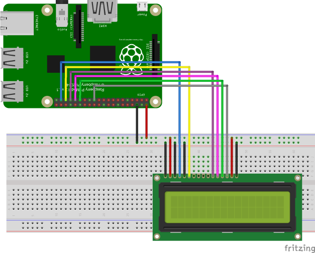
As you can see from the wiring diagram, the LCD will take up around 6 GPIO pins on your Raspberry PI. If you have some modules plugged in or you are planning to then there are chances that you will fall short of the GPIO pins. To save GPIO pins on your board, you can use MCP23008 or MCP23017 . To keep it simple, I am not using any port expanders for now.
Now comes the code, I have a very little knowledge of Python at the moment. So I am going to stick with what I have read and tested. For controlling the LCD, I am going to use Adafruit’s LCD library which you can get it from Github here. I am going to use Adafruit_CharLCD.py to control my LCD. The thing to keep in mind is that you cannot use this library out of the box. You have to make a change to set the correct GPIO pins in the __init__ function. Open the file using the below command.
$ sudo nano Adafruit_CharLCD.py
If you are using the same wiring as I am, then change the __init__ function like this
def __init__init(self, pin_rs=26, pin_e=19, pins_db=[13, 6, 5, 11], GPIO=None):
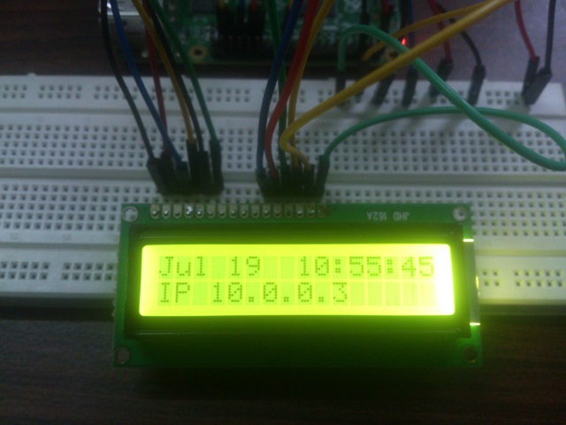
Save the changes and we are good to go. To check if the wiring and the code changes are done properly, execute the below command in the same directory.
$ sudo ./Adafruit_CharLCD_IPclock_example.py
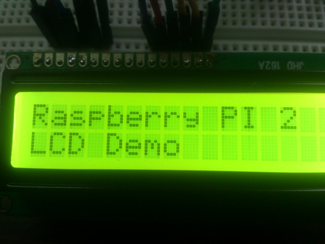
Let’s try displaying some custom messages to the display with this simple program.
from Adafruit_CharLCD import Adafruit_CharLCD

lcd = Adafruit_CharLCD()
lcd.message("Raspberry PI 2\nLCD Demo")
Here is one more. The program will ask you to enter the string to display.
from Adafruit_CharLCD import Adafruit_CharLCD

lcd = Adafruit_CharLCD()

#Getting input from user
msg = raw_input("Enter message to display\n")

#Display it on the LCD
lcd.message(str(msg))
The reason I am using Adafruit library to control the display is because it has other useful functions to control LCD. Here is the list of functions that you can try.
clear() - Clears the LCD and remove text from the memory.
display()/noDisplay() - Toggle the text visibility on the LCD. Text remains in the memory.
cursor()/noCursor - Toggle cursor visibility.
blink()/noBlink() - Toggle cursor blink.
home() - Take the cursor to the 0,0 position i.e. first column of first row.
setCursor(col, row) - Set the cursor to the specific position. Use lcd.begin(col, rows) to set the number of columns and rows your display has.
I hope this will be useful to the people who are just getting started with Raspberry Pi. You can also download the complete source code from Github here.